2.6″ TFT-lcd (320*240) SPI Arduino Mega 2560 *mcufriend*
so,
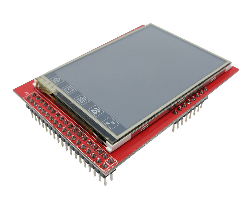
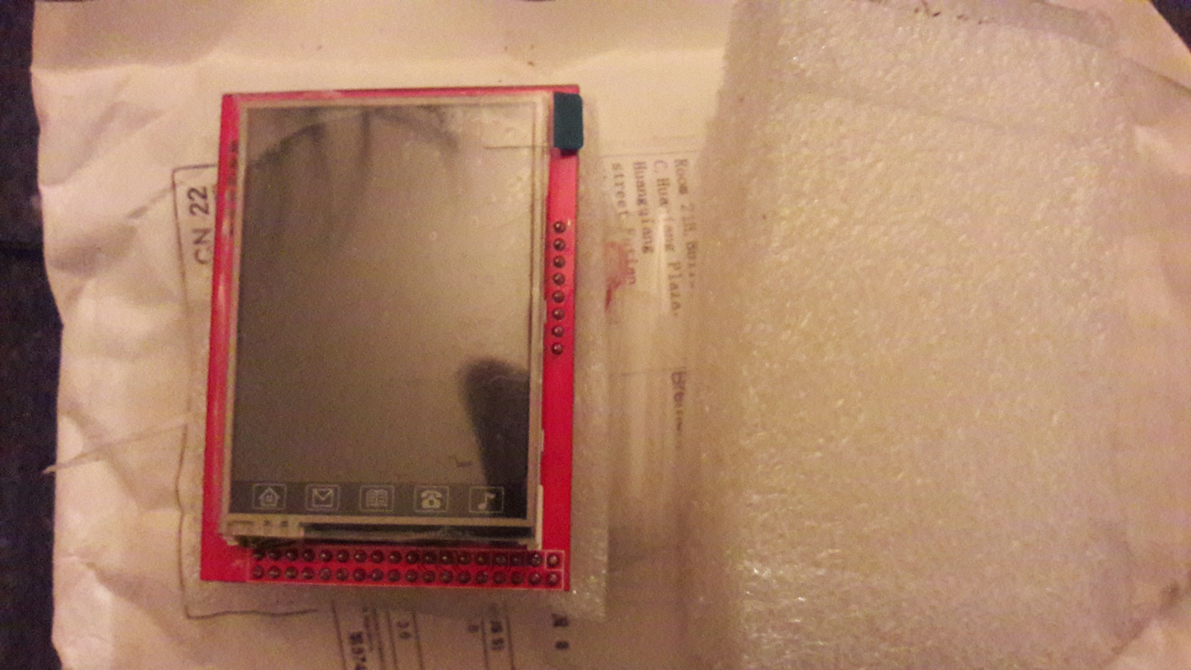
lucky me, i got today my 2.6″ (320*240) SPI-TFTLCD-display directly from china, of about 3,40€ !! 😉 (inclusive shipping), unbelievable, from Aliexpress..
all in regard of my planned DIY-DAC (see some posts before and therefore the website is all about 😉 ), cause this TFT-LCD should show the input-source (USB,Coax,Opt.), sampling frequency, filter settings (FIRs), Volume (db) and so on..
okay, there was no information on the sellers-site about the chipset in it (and i need the info for the different Arduino+Raspberry GFX-libraries) i had to google a lot and will now show the “results”:
First, in this special TFT is an “ILI9341“; read out on a RPI3B with “fbtft_device”->

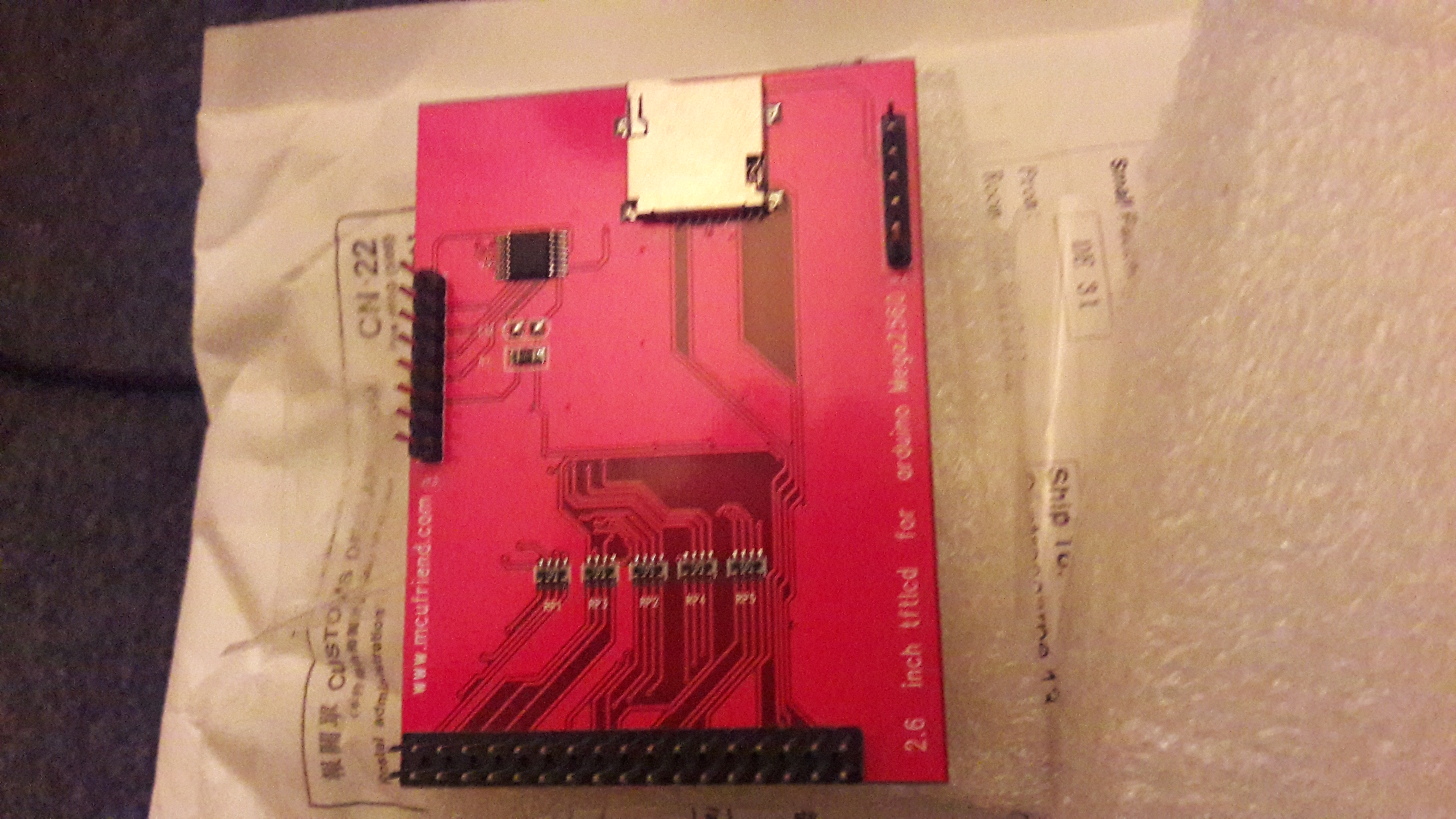
second, problem now was, because there were absolute no documentation about the pin-layout on the backside, how to wire it for SPI ?
so, a lot of googling again and here are the results Part II.:
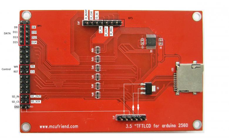
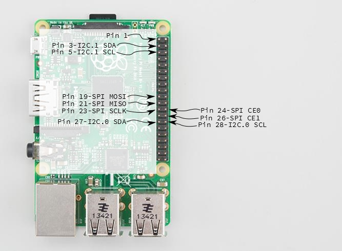
so, my final wiring is now:
3,3V (5V is not working) Pin5 from the 6pin header at the bottom->to RPI Pin1 (Power)
GND Pin2 from the 6pin header->RPI Pin9
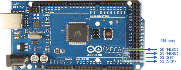
MOSI to MOSI !! means “SD_in” on the first picture -> RPI pin19
MISO to MISO means “SD_Out” ->RPI pin21
CS to “SD_CS” ->RPI pin24 !! (CE0) ((not pin26)->CE1)
and SCLK to “SD_SCK” ->RPI pin23..
(unfortunately i have only a light screen here now, but i guess it has something to do with the software; i will make here an update if necessary)..
(just as info for other user with similar problems)..
good tuturial: SPI on a raspberry pi->https://www.xgadget.de/anleitung/2-2-spi-display-ili9341-am-raspberry-betreiben/