DSD-LED (+Volume and FIR-Buttons) on these ES9028Q2M-Boards..(DIY)
so,
because here is so much feedback/and website-views on this ES9028Q2M i thought i write something about it again..
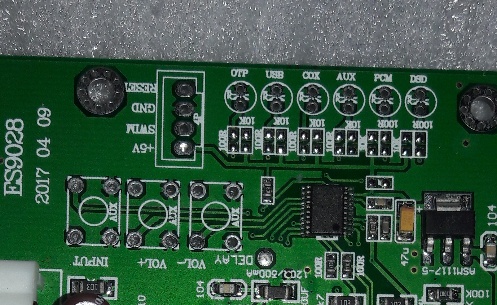
after thinking about programming this STM 8S103F3 MCU on the board (and see some Arduino IDE tuturials to become a LED blinking par example->https://learn.sparkfun.com/tutorials/sik-experiment-guide-for-arduino—v32/experiment-1-blinking-an-led , super nice a MUST to watch !! 😉 ) and examining the layout i see that there are also these “Vol+”,”Vol-“, “Delay” (means filter-settings (FIRs) i think) and the “DSD” + “PCM” holes for Diodes/LEDs..
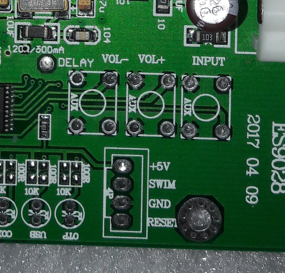
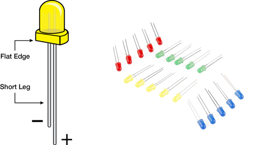
so i think u need only an LED (i would say Blue for DSD and Red for PCM) and a 220 Ohm-Resistor->
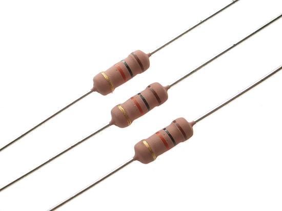
to make this LEDs “shine” 😉
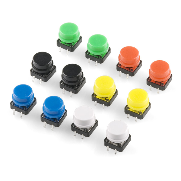
also with such Buttons (here i had measurements about 1cm*0,7cm (100mm*70mm)) it must be possible to have a HW-Volume and Filter-Control..
but u have to solder it right 😉 ..
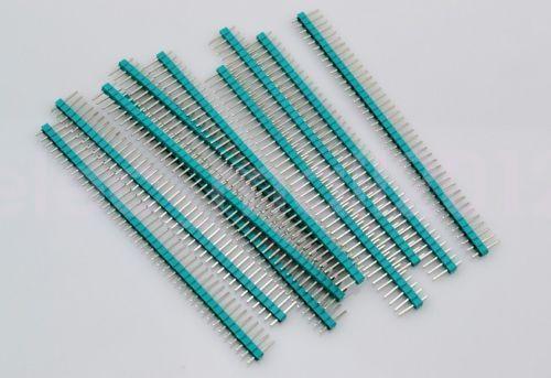
another possibility would also be to solder some 4 Male 2.54mm Pin Header on it, and connect it then to a STM32F103C8T6 by example to control it via this (and with a bluetooth-receiver-transmitter and bluetooth-app par example..)
still thinking about; greets for the moment 😉