DIY: Relay-controlled source-/filter selection ES9038Q2M (Arduino)
so, 😉
because i´m really stupid and really don´t know how to accomplish a “jumper-substitution” and after reading in some Arduino-forums, i came to the idea of buying some relay and try to realise it via this way..
(Update: “profd” from the forum told “us” to use digi high or low + a logic level converter instead;->LINK)
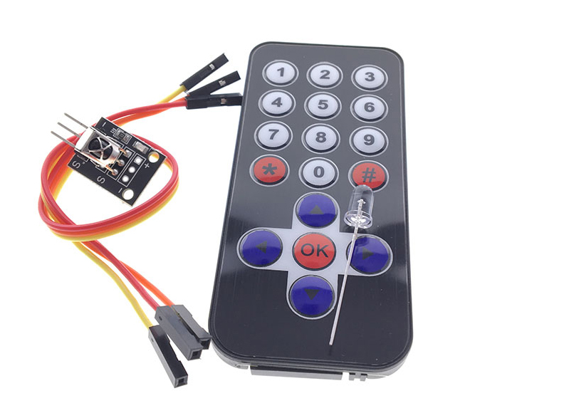
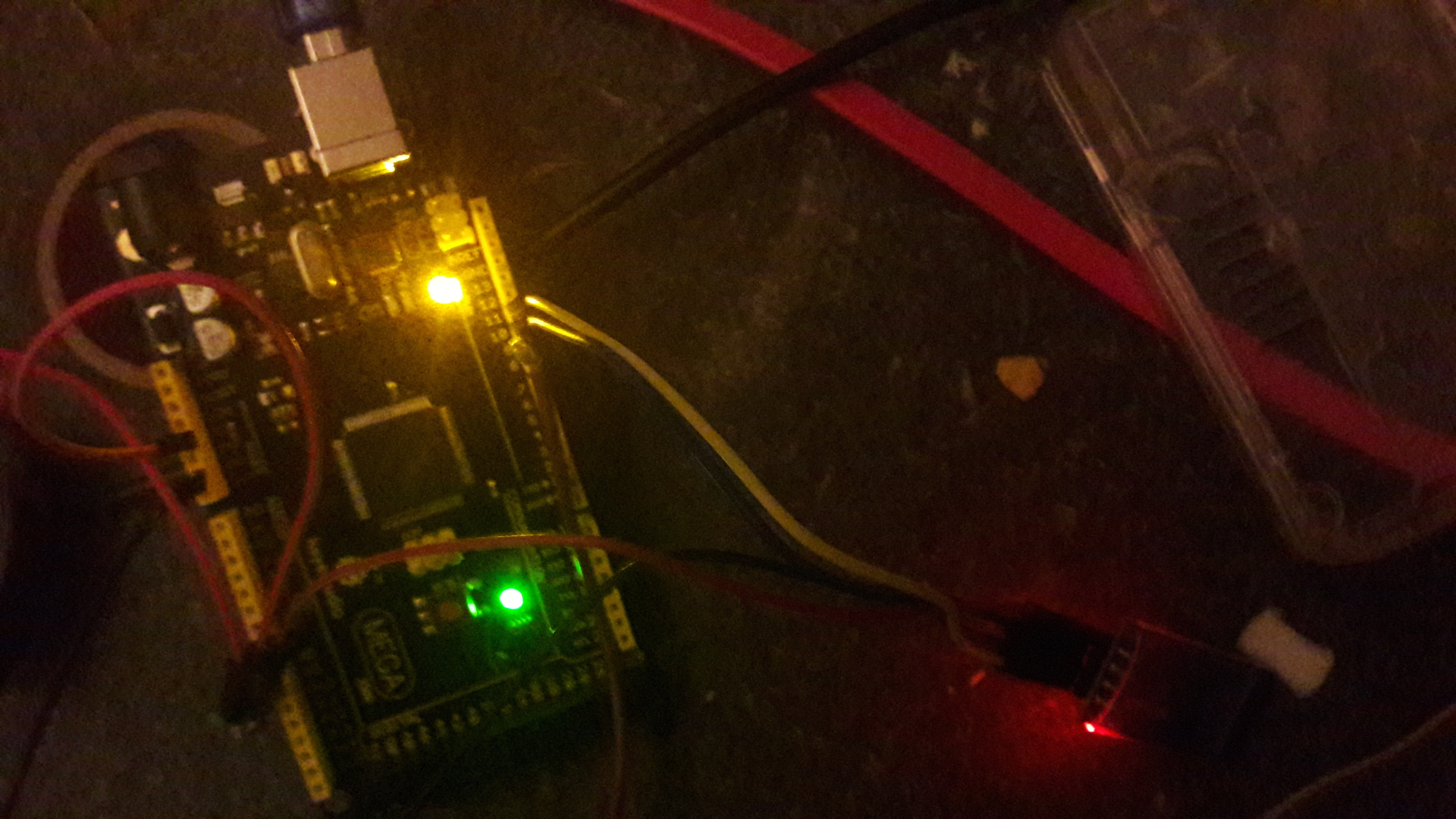
These relays are cheap, around 2€ or so, u can buy it as 1,2,4,8 and so on..they are really easy to connect/addressable..

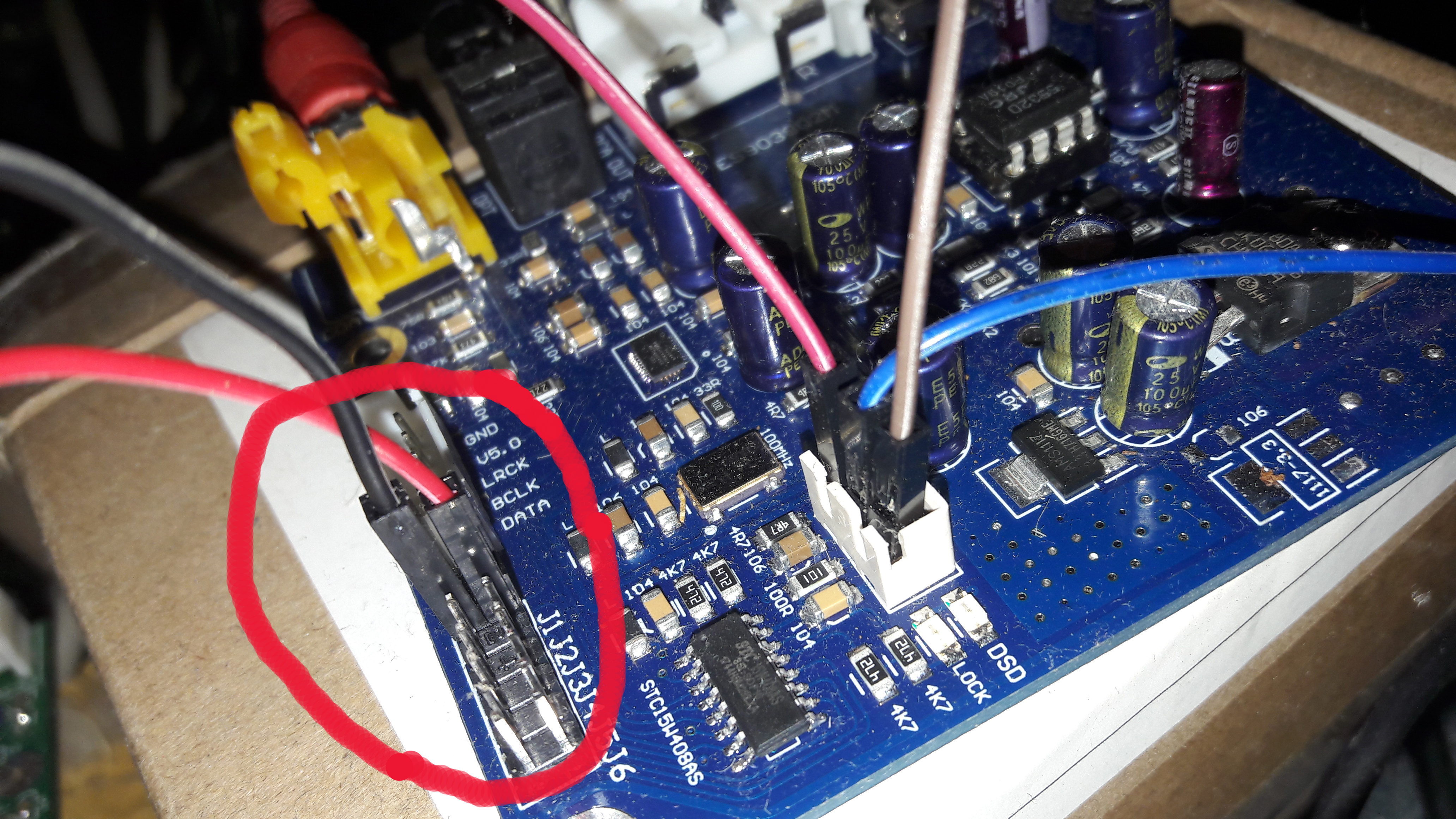
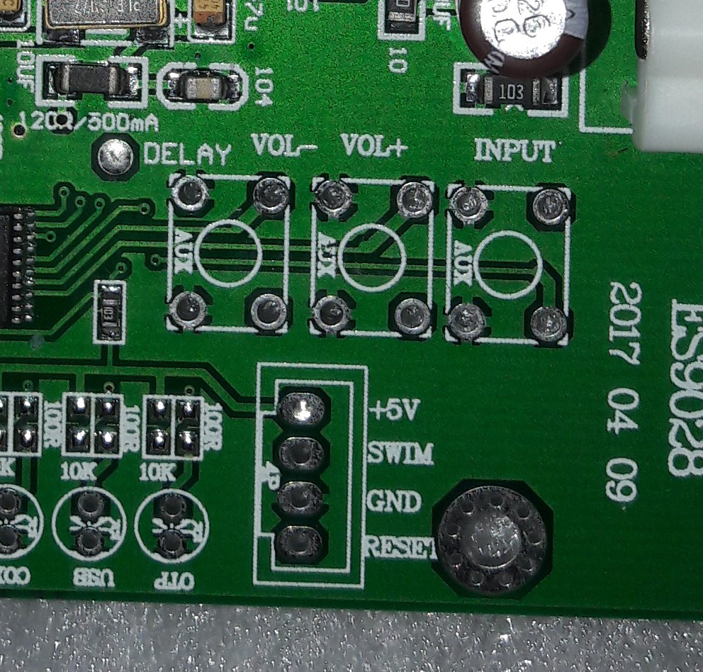
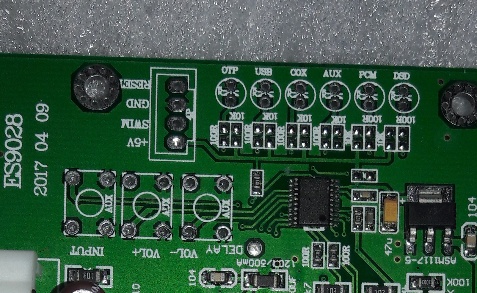
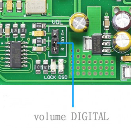
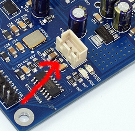
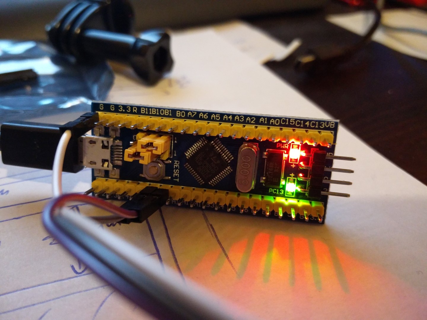
(remark: the 3 wires on the right are for the 10k poti (and then in future for the digi-poti of course))

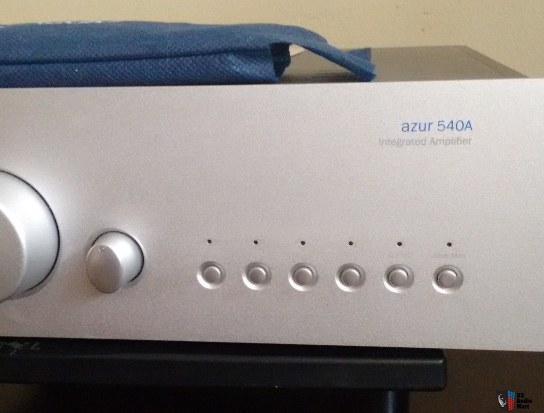
u connect the GND and + from JP1 on the ES9038Q2M to COM (GND) and NO (+) and thats it..(i first connected it to the NC (normally closed) but that means, if u shut the Arduino down, then the circuit is (normally-)”closed”, means jumper set..
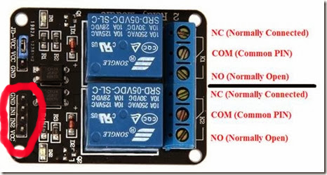
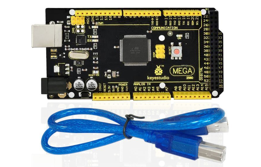
the relay itself is easy connected; GND from the Arduino to the GND and Power (5V+) from the Arduino to the VCC-pin (the jumper JD-VCC etc.. is another story, only remove and connect it to an external power source if u want to separate the Arduino-circuit completely from the relais circuit).
IN1,IN2 etc. is connected to a pin of your choice/assignment made in the sketch like this:
//relais
#define RELAY1 8
#define RELAY2 12
#define RELAY3 6
#define RELAY4 7
(i will post the modified sketch in the forum->LINK)
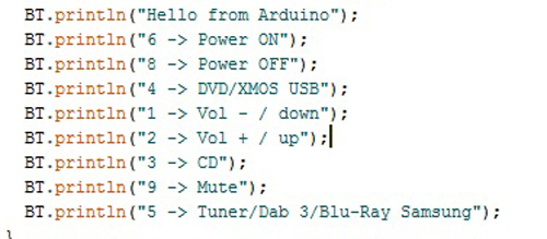
so, and now i can control/set the source via the BT (via our sketch), means for example “c” for coaxial, “o” for optical, “i” for I2S and so on..
if (a==’c’)
{
BT.println(“Source: coaxial”);
digitalWrite(RELAY2,HIGH); //R2 OFF
delay(50);
digitalWrite(RELAY1,LOW); //R1 ON
..
lcd.print(“Source: coaxial”);
}
i, u, can also use this now to set the different-filter-types, as for example JP3=set and JP4=set ->”slow minimum roll off filter”)..(will also maybe make a modified sketch for this future..)..
so, and really funny/cool 😉 is that these relays really make a “clack”-noise, everytime u adress it, for example i choose “c”=coaxial it makes “clack” and it changes to coaxial..
really “Hi-Fi” 😉
(forum-link->LINK)


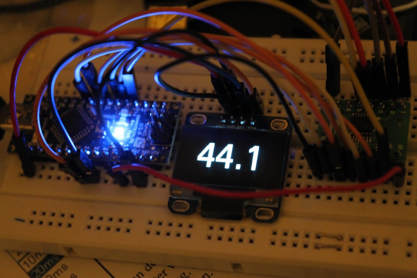
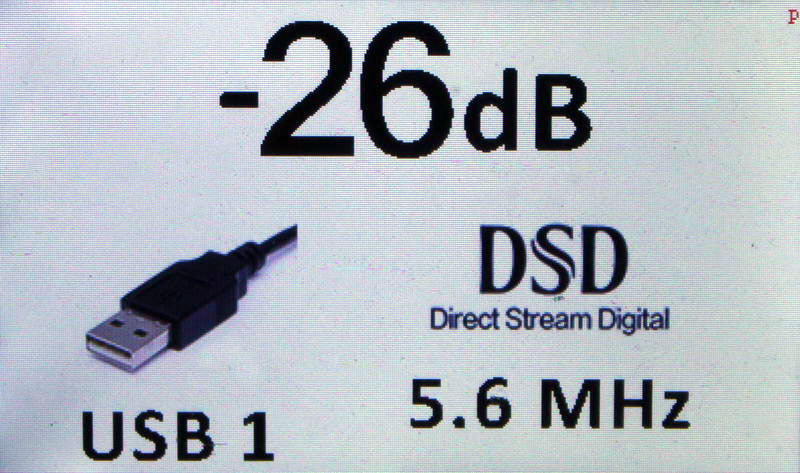
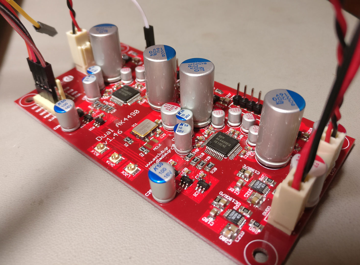 (picture courtesy/copyright http://dimdim.gr)