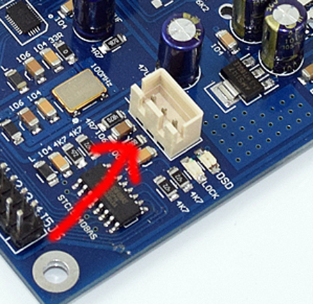
ES9038Q2M: I2C-connection/TFTLCD-displays SDA/SCL

so, 😉
came by chance about this “new feature”; had read about it but forgot it; its from this forum->http://audiodiyers.hu/viewtopic.php?f=48&t=3615&sid=3d4bd2f2c89af6709dfbbe53ec0a9ee3&start=50#p74779
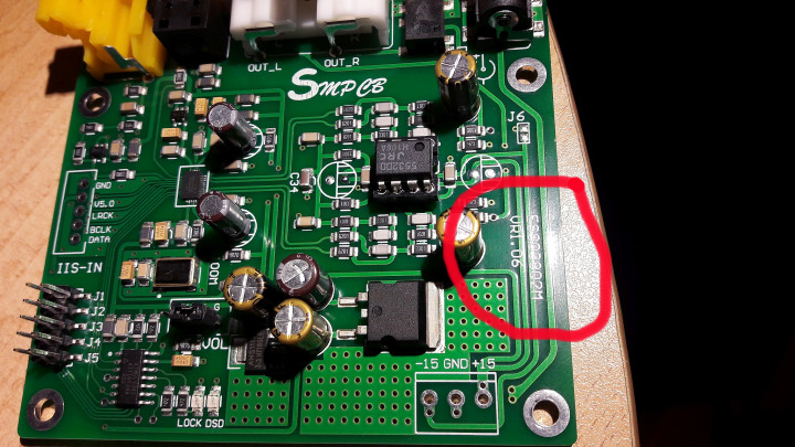
means we can expect a “panel” (over I2C !!) for it->”..the backpanel was developed by the end of february..”(VR1.06)
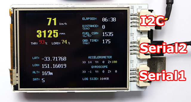
and there were several panel/options via I2C->not only 16*2, also 128*64, 320*240 and so on !! 😉


https://freematics.com/pages/products/tft-lcd-shield-3-2/

try at present to test out some libraries for this..

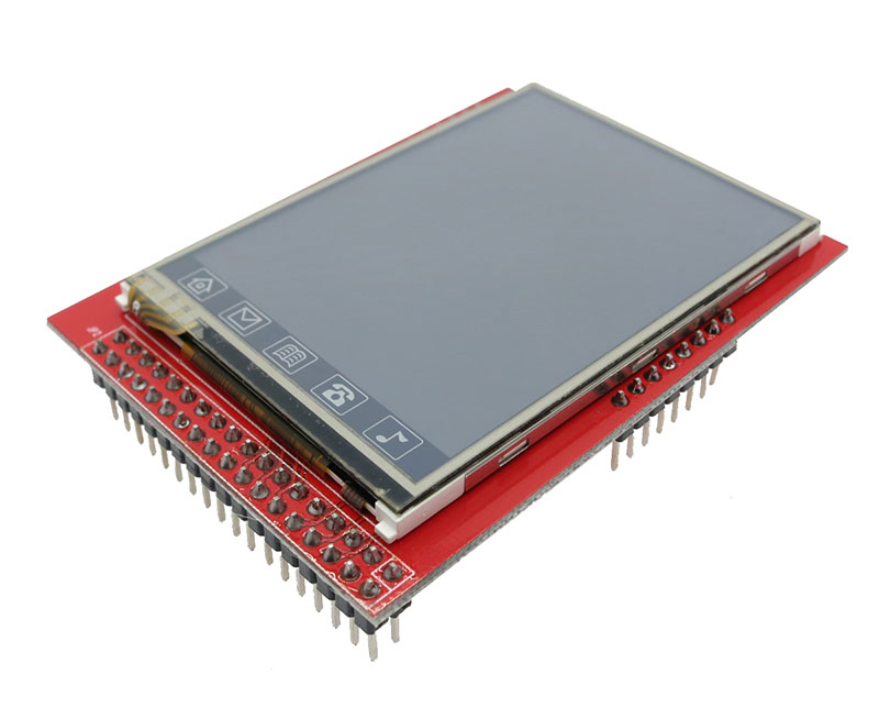
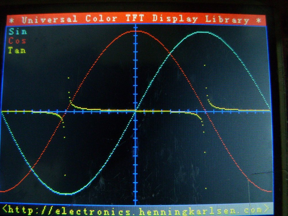
DIY: First tests 2.6″ TFTLCD (320*240) Arduino UTFT-library..

so, 😉
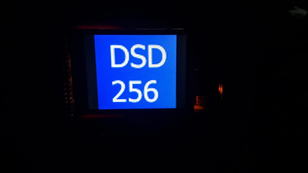
see above..absolutely “low” 😉 , but as test->UTFT-font is: “GroteskBold32X64”->http://www.rinkydinkelectronics.com/r_fonts.php

“wait,wait,wait..but for what ?” 😉

(i will try to use some bitmaps/icons in future (like in the hifi-duino-project) but at present its really difficult for me to “include” them/set them up in the sketch, also because of the very low ram-resources on an arduino (on a NodeMCU v3 for example u have up to 32MB flash and not max 256kb!! like on an Arduino (Mega2560))-there are some ways to optimize it, but for now i´m glad to got it to work at all 😉 )

DIY: Relay-controlled source-/filter selection ES9038Q2M (Arduino)

so, 😉
because i´m really stupid and really don´t know how to accomplish a “jumper-substitution” and after reading in some Arduino-forums, i came to the idea of buying some relay and try to realise it via this way..

(Update:profd” from the forum told “us” to use digi high or low + a logic level converter instead;->LINK)
These relays are cheap, around 2€ or so, u can buy it as 1,2,4,8 and so on..they are really easy to connect/addressable..

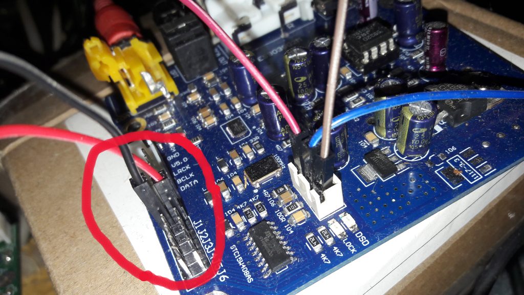
(remark: the 3 wires on the right are for the 10k poti (and then in future for the digi-poti of course))
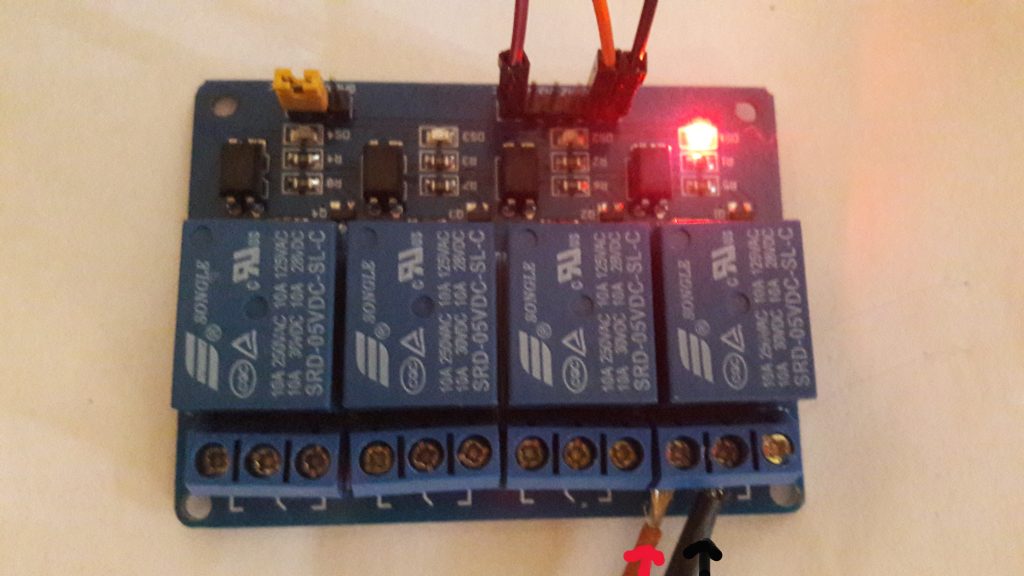
u connect the GND and + from JP1 on the ES9038Q2M to COM (GND) and NO (+) and thats it..(i first connected it to the NC (normally closed) but that means, if u shut the Arduino down, then the circuit is (normally-)”closed”, means jumper set..
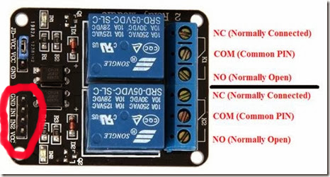
the relay itself is easy connected; GND from the Arduino to the GND and Power (5V+) from the Arduino to the VCC-pin (the jumper JD-VCC etc.. is another story, only remove and connect it to an external power source if u want to separate the Arduino-circuit completely from the relais circuit).
IN1,IN2 etc. is connected to a pin of your choice/assignment made in the sketch like this:
//relais
#define RELAY1 8
#define RELAY2 12
#define RELAY3 6
#define RELAY4 7
(i will post the modified sketch in the forum->LINK)
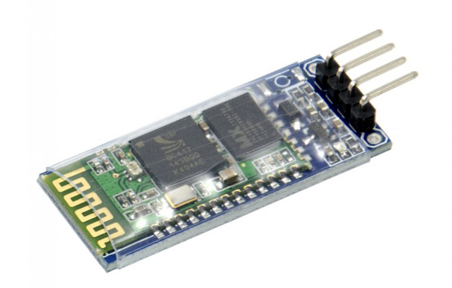
so, and now i can control/set the source via the BT (via our sketch), means for example “c” for coaxial, “o” for optical, “i” for I2S and so on..

if (a==’c’)
{
BT.println(“Source: coaxial”);
digitalWrite(RELAY2,HIGH); //R2 OFF
delay(50);
digitalWrite(RELAY1,LOW); //R1 ON
..
lcd.print(“Source: coaxial”);

}

i, u, can also use this now to set the different-filter-types, as for example JP3=set and JP4=set ->”slow minimum roll off filter”)..(will also maybe make a modified sketch for this future..)..
so, and really funny/cool 😉 is that these relays really make a “clack”-noise, everytime u adress it, for example i choose “c”=coaxial it makes “clack” and it changes to coaxial..


really “Hi-Fi” 😉

(forum-link->LINK)
DIY: 2.6″ TFT-LCD (320*240) SPI ARDUINO MEGA 2560 *MCUFRIEND* (Part2) **works**

so, 😉
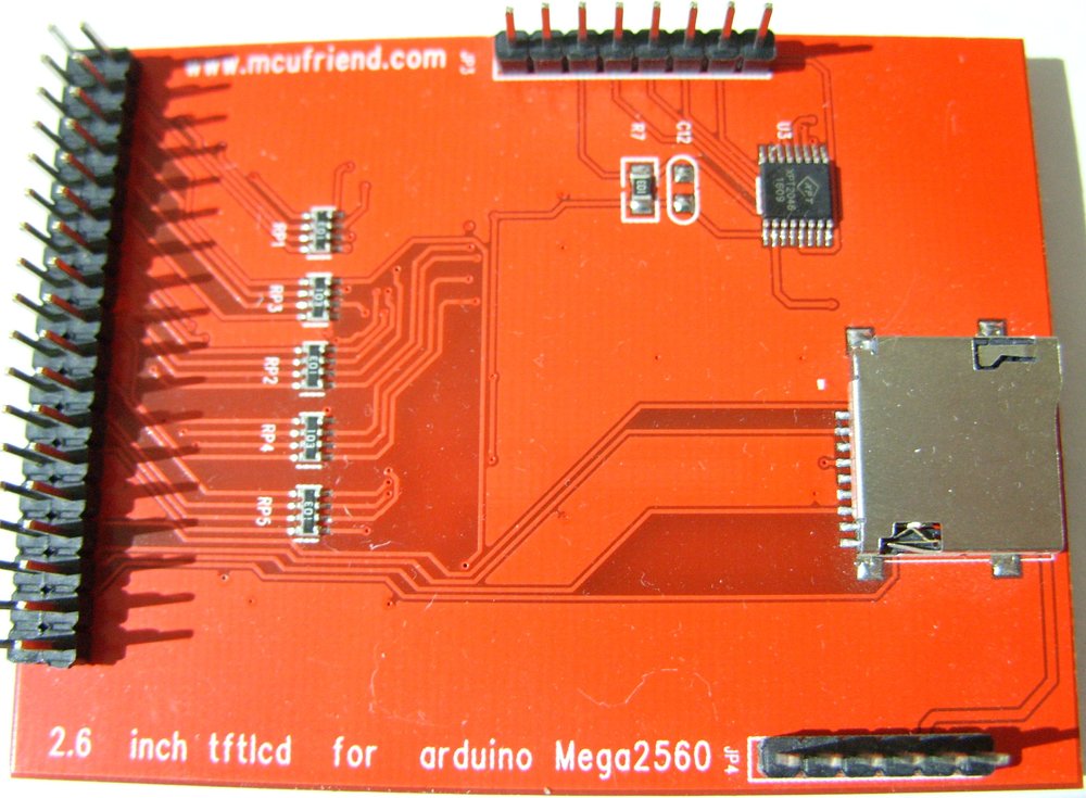
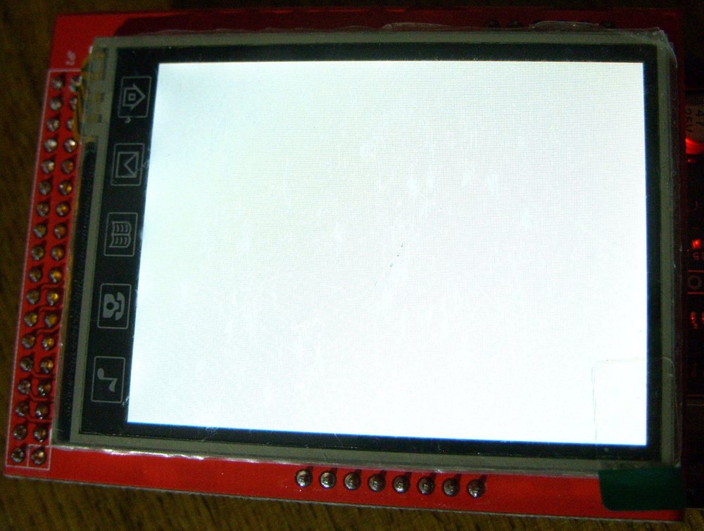
got the above mentioned 2.6″ tftlcd finally to work !! 😉

(3,40€->https://de.aliexpress.com/item/LCD-module-TFT-2-6-inch-TFT-LCD-screen-for-Arduino-Mega2560-R3-Board/32716341280.html)

see this (Part1)->http://essabre-90xx-rpi.sfb2.com/2017/11/2-6-tft-lcd-320240-spi-arduino-mega-2560-mcufriend/
and this new post in the forum->http://essabre-90xx-rpi.sfb2.com/forum/showthread.php?tid=29
the “breakthrough” was via this site->http://forum.cxem.net/index.php?/topic/197765-26-inch-tftlcd-for-arduino-mega-2560-unknoun-driver/
(i got the chip/controller ID:”0x0404“)
and this very,very important,modified library->http://www.sfb2.com/pics/UTFT_for_ST7781.rar

(more, full article/post/tut in the forum)

DIY: Migration sketch/build-up Arduino Mega2560 to Uno R3

so, 😉
hello, nothing new in particular..got today my “Geekcreit® UNO R3 ATmega328P” for roundabout 3€ (i order there sometimes because of (in general) faster shipping times then Aliexpress)->
https://www.banggood.com/UNO-R3-ATmega328P-Development-Board-For-Arduino-No-Cable-p-964163.html

nothing special, except u have to use “Pin3” instead of “Pin9” on the Mega2560 for irsend..
(made a long post in the forum->http://essabre-90xx-rpi.sfb2.com/forum/showthread.php?tid=28)

greets 😉

ES9038Q2M: “Project 2”->building a BT-controlled HW-Volume-control (digital pot 10kOhm) MCP4131

so, 😉
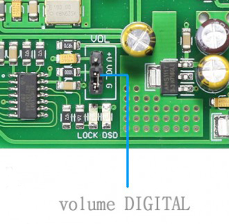
because its a little bit silent around here lately, we still don´t know if the “Blue” ES9038Q2M has a “shitty” pcb and the “green”-ones sounds better, i have still buffer/”lock”-problems in windows using the V4.36 Singxer-driver on the Skysong-XMOS-USB in sample rates above 16/44 i wanted to use the onboard-HW-volume control, to which u can connect a normal 10kOhm-potentiometer (see pictures) easy..


i tested it here, and it works far not so good as expected and i guess u have a very small range of about 20% or so (in my feel) too..
i thought i could easy use the Arduino with analogwrite () and connect one pin to the middle of the onboard-3 pin but what i´ve read so far is that the Arduino can only send out PWM-signals so u need an external digital potentiometer (thats what i´ve read so far, don´t know if its true) and control it via the (in this case) SPI-bus/protocol..
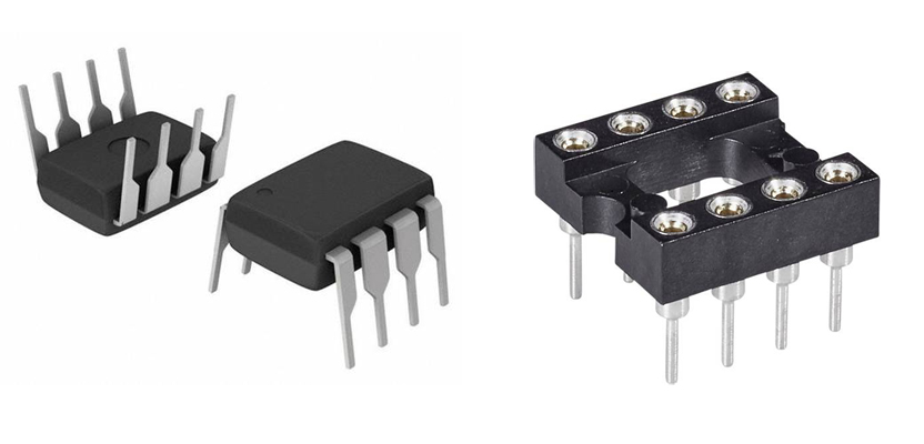
for this u can buy a cheap MCP, in this case a MCP4131 of around 0,89€ and a Dip-8 socket (0,51€) etc.,etc..(more to come..)


(very good tutorial for this right now:
http://www.learningaboutelectronics.com/Articles/MCP4131-digital-potentiometer-circuit.php)

i will post here any “improvements” (and (maybe) a full tut) asap..!! 😉

DIY: LCD1602+I2C modul..(sketches+links)

so, 😉
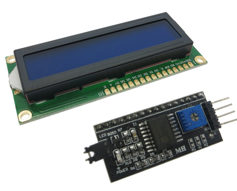
today, after 60 !! days, my LCD1602+I2C-modul finally arrived..(2.00$ Aliexpress->LINK)


i have already a 2.6″ TFT-LCD display (320×240), but also want to check these 1602-LCDs (its “standard” for the “real”-Arduino-User 😉 )
okay, there is not soo much to tell, except that i havent bring it to work in “full mode” so far because (and thats why i write this article here too) it was the “hell again” 😉 soldering the I2C-modul (in this case i took a 16pin pin-strip) on the LCD-PCB..
so if u can find a 1602-LCD with a I2C-modul already soldered on it, take it ;-)..
i extended my Bluetooth-IR-sketch now with a “blink” from the whole display (” lcd.backlight(); delay(250); lcd.noBacklight(); delay(250);” 😉 everytime i make a command, type a “value” via the Bluetooth-App; as confirmation..
Its blue and i first thought i print the source (“CD,DVD,XMOS-USB etc..)” on it; but there are no characters on it by now cause i guess i have to solder some pins again ;-(..
useful sketches i´ve found so far were:”identify the I2C-adress from the modul (“i2c_adress.ino”) and a simple sketch to get data via the serial monitor and print it on the screen..(.inos and links here->http://essabre-90xx-rpi.sfb2.com/forum/showthread.php?tid=19 )

so far so good, many greets from here 😉

1 2 3 4 5